Thyristor-Module MT3, MT4, MT5

Leistungs-SRC-Doppelthyristor-Module MT AS ENERGITM sind eine monolithische Konstruktion mit zwei Halbleiter-Thyristoren (Typ thyristor-thyristor), arbeiten in Gleich- und Wechselstromkreisen mit Lasten von 115A bis zu 1250A und Rückwärtsimpulsspannungen bis zu 6500V.
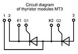
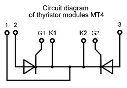
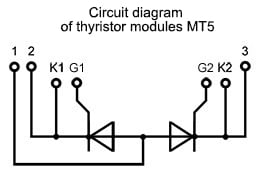
Anschlussplan von Modulen: MT3 – Halb-Brücke; MT4 – Kollektivkathodenschaltung; MT5 – gemeinsame Anodenschaltung.
Hoch energie-thermozyklischer Widerstand und zuverlässigen Betrieb von niederfrequenten Thyristor-Modulen von MT beim Schalten hoher Ströme wird durch ihre Konstruktionsmerkmale und stabile Parameter galvanische Trennung:

- die Durchschlagsfestigkeit der Isolierung zwischen der potentialfreien Basis und den Leitungen die Marke erreicht 3600V unter normalen klimatischen Bedingungen und 1500V bei hoher Luftfeuchtigkeit;
- Das Gehäuse besteht aus nicht brennbares Thermopolymer;
- die Spannungsfestigkeit der Isolierung zwischen Haupt- und Steuerleitung erreicht die Marke von 2500V unter normalen klimatischen Bedingungen und 1500V bei hoher Luftfeuchtigkeit;
- der Isolationswiderstand zwischen der potentialfreien Basis und den Ausgängen unter normalen klimatischen Bedingungen mindestens 50МОм und nicht weniger als 5МОм bei hoher Luftfeuchtigkeit;
- der Isolationswiderstand zwischen Haupt- und Steuerleitung unter normalen klimatischen Bedingungen mindestens 1000МОм und nicht weniger als 100МОм bei hoher Luftfeuchtigkeit;
Die Thyristor-Module MT3, MT4, MT5 haben eine Klemmkonstruktion, Montage mit Schrauben durch die durchgehenden Befestigungslöcher im Gehäuse. Die Drähte sind mit vernickelten Klemmen befestigt, unter denen die Prüfpunkte zur Messung der Impulsgleichspannung angebracht sind. Hauptleitungen befinden sich auf der Oberseite des Gehäuses und sind nummeriert 1, 2, 3. Steuerleitungen sind im Diagramm gekennzeichnet als G1, G2. Zusatzkathoden sind im Diagramm gekennzeichnet als K1, K2.
Bei der Montage von Thyristor-Modulen ist besonders auf die Dichtheit der Passflächen – Eine Konkavität von mehr als 0,03 mm ist nicht zulässig.
Zum Anbringen zusätzliche Kühlung (Heizkörper oder Kühler werden verwendet), Im Gehäuse der potentialfreien Thyristor-Module sind Befestigungslöcher vorgesehen. Zwischen dem Modul und dem Kühlelement muss ein spezielles wärmeleitendes Substrat verwendet werden, das mit Wärmeleitpaste geschmiert ist.
Thyristor-Module MT3, MT4, MT5 verwendet werden in verschiedenen Energieanlagen - Leistungs- und Steuereinheiten, Leistungsregler, Wechselstromregler, Wechselrichter, Motorstarter und -steuerungen, Temperaturregler für Hochöfen oder chemische Prozesse, Schweißgeräte usw.
Unsere Module werden in verschiedenen Dual- und Single-Device-Topologien für fast alle Phasensteuerungs- oder Gleichrichteranwendungen angeboten.
Unser Unternehmen bietet eine Qualitätsgarantie für Thyristor-/Dioden-Module von 2 Jahren ab dem Kaufdatum. Bei der Lieferung von Thyristor / Dioden-Module, falls erforderlich, bieten wir technischen Pass und Konformitätsbescheinigung.
Der Endpreis für Thyristor/Dioden-Module hängt von der Klasse, der Menge, den Lieferbedingungen, dem Hersteller, dem Herkunftsland und der Zahlungsart ab.
Bei Fragen zum Erwerb von SCR-Thyristoren, Dioden, Modulen senden Sie eine E-Mail-Anfrage an:
Und wir unterbreiten Ihnen ein kommerzielles Angebot für die Lieferung.
Bei großen Stückzahlen erstellen wir einen individuellen Preis!!!
Wir sind offen für die Herstellung von Produkten in unseren Produktionsstätten nach Ihren Wünschen und technischen Aufgabenstellungen.
Allgemeine Spezifikationen von Thyristor-Thyristor-Modulen MT3, MT4, MT5
| Foto | Serie | Durchschnittlicher Durchlassstrom, IT(AV) |
Spannung, VRRM |
Anschlussplan | Paket | Abmessungen | |
 |
MT3-115 | 115A | 3000 - 3600V |  |
F | 94x34x30 | |
 |
MT4-115 | 115A | 3000 - 3600V |  |
F | 94x34x30 | |
 |
MT3-125 | 125A | 2400 - 2800V |  |
F | 94x34x30 | |
 |
MT4-125 | 125A | 2400 - 2800V |  |
F | 94x34x30 | |
 |
MT3-130 | 130A | 2400 - 2800V |  |
F | 94x34x30 | |
 |
MT4-130 | 130A | 2400 - 2800V |  |
F | 94x34x30 | |
 |
MT3-160 | 160A | 2000 - 2200V |  |
F | 94x34x30 | |
 |
MT3-160 | 160A | 3000 - 3600V |  |
C1 | 92x52x50 | |
 |
MT4-160 | 160A | 2000 - 2200V |  |
F | 94x34x30 | |
 |
MT4-160 | 160A | 3000 - 3600V |  |
C1 | 92x52x50 | |
 |
MT5-160 | 160A | 3000 - 3600V |  |
C1 | 92x52x50 | |
 |
MT3-165 | 165A | 2000 - 2200V |  |
F | 94x34x30 | |
 |
MT4-165 | 165A | 2000 - 2200V |  |
F | 94x34x30 | |
 |
MT3-200 | 200A | 1000 - 1800V |  |
F | 94x34x30 | |
 |
MT3-200 | 200A | 2600 - 2800V |  |
C1 | 92x52x50 | |
 |
MT4-200 | 200A | 1000 - 1800V |  |
F | 94x34x30 | |
 |
MT4-200 | 200A | 2600 - 2800V |  |
C1 | 92x52x50 | |
 |
MT5-200 | 200A | 2600 - 2800V |  |
C1 | 92x52x50 | |
 |
MT3-201 | 201A | 1000 - 1800V |  |
F | 94x34x30 | |
 |
MT4-201 | 201A | 1000 - 1800V |  |
F | 94x34x30 | |
 |
MT5-201 | 201A | 1000 - 1800V |  |
F | 94x34x30 | |
 |
MT3-240 | 240A | 4600 - 6500 |
 |
A2 | 124x60x52 | |
 |
MT4-240 | 240A | 4600 - 6500V |  |
A2 | 124x60x52 | |
 |
MT5-240 | 240A | 4600 - 6500V |  |
A2 | 124x60x52 | |
 |
MT3-250 | 250A | 2000 - 2400V |  |
C1 | 92x52x50 | |
 |
MT3-250 | 250A | 3800 - 4400V |  |
A2 | 124x60x52 | |
 |
MT4-250 | 250A | 2000 - 2400V |  |
C1 | 92x52x50 | |
 |
MT4-250 | 250A | 3800 - 4400V |  |
A2 | 124x60x52 | |
 |
MT5-250 | 250A | 2000 - 2400V |  |
C1 | 92x52x50 | |
 |
MT5-250 | 250A | 3800 - 4400V |  |
A2 | 124x60x52 | |
 |
MT3-260 | 260A | 3800 - 4400V |  |
A2 | 124x60x52 | |
 |
MT4-260 | 260A | 3800 - 4400V |  |
A2 | 124x60x52 | |
 |
MT5-260 | 260A | 3800 - 4400V |  |
A2 | 124x60x52 | |
 |
MT3-320 | 320A | 1000 - 1800V |  |
C1 | 92x52x50 | |
 |
MT3-320 | 320A | 3000 - 3600V |  |
A2 | 124x60x52 | |
 |
MT4-320 | 320A | 1000 - 1800V |  |
C1 | 92x52x50 | |
 |
MT4-320 | 320A | 3000 - 3600V |  |
A2 | 124x60x52 | |
 |
MT5-320 | 320A | 1000 - 1800V |  |
C1 | 92x52x50 | |
 |
MT5-320 | 320A | 3000 - 3600V |  |
A2 | 124x60x52 | |
 |
MT3-400 | 400A | 2000 - 2800V |  |
A2 | 124x60x52 | |
 |
MT3-400 | 400A | 3800 - 4400V |  |
D | 150x77x84 | |
 |
MT4-400 | 400A | 2000 - 2800V |  |
A2 | 124x60x52 | |
 |
MT4-400 | 400A | 3800 - 4400V |  |
D | 150x77x84 | |
 |
MT5-400 | 400A | 2000 - 2800V |  |
A2 | 124x60x52 | |
 |
MT5-400 | 400A | 3800 - 4400V |  |
D | 150x77x84 | |
 |
MT3-430 | 430A | 2000 - 2400V |  |
A2 | 124x60x52 | |
 |
MT4-430 | 430A | 2000 - 2400V |  |
A2 | 124x60x52 | |
 |
MT5-430 | 430A | 2000 - 2400V |  |
A2 | 124x60x52 | |
 |
MT3-500 | 500A | 1400 - 1800V |  |
A2 | 124x60x52 | |
 |
MT3-500 | 500A | 3000 - 3600V |  |
D | 150x77x84 | |
 |
MT4-500 | 500A | 1400 - 1800V |  |
A2 | 124x60x52 | |
 |
MT4-500 | 500A | 3000 - 3600V |  |
D | 150x77x84 | |
 |
MT5-500 | 500A | 1400 - 1800V |  |
A2 | 124x60x52 | |
 |
MT5-500 | 500A | 3000 - 3600V |  |
D | 150x77x84 | |
 |
MT3-540 | 540A | 1400 - 1800V |  |
A2 | 124x60x52 | |
 |
MT4-540 | 540A | 1400 - 1800V |  |
A2 | 124x60x52 | |
 |
MT5-540 | 540A | 1400 - 1800V |  |
A2 | 124x60x52 | |
 |
MT3-595 | 595A | 1400 - 1800V |  |
A2 | 124x60x52 | |
 |
MT4-595 | 595A | 1400 - 1800V |  |
A2 | 124x60x52 | |
 |
MT5-595 | 595A | 1400 - 1800V |  |
A2 | 124x60x52 | |
 |
MT3-630 | 630A | 1000 - 1200V |  |
A2 | 124x60x52 | |
 |
MT3-630 | 630A | 2600 - 2800V |  |
D | 150x77x84 | |
 |
MT4-630 | 630A | 1000 - 1200V |  |
A2 | 124x60x52 | |
 |
MT4-630 | 630A | 2600 - 2800V |  |
D | 150x77x84 | |
 |
MT5-630 | 630A | 1000 - 1200V |  |
A2 | 124x60x52 | |
 |
MT5-630 | 630A | 2600 - 2800V |  |
D | 150x77x84 | |
 |
MT3-650 | 650A | 1000 - 1200V |  |
A2 | 124x60x52 | |
 |
MT4-650 | 650A | 1000 - 1200V |  |
A2 | 124x60x52 | |
 |
MT5-650 | 650A | 1000 - 1200V |  |
A2 | 124x60x52 | |
 |
MT3-700 | 700A | 1400 - 1800V |  |
A2 | 124x60x52 | |
 |
MT4-700 | 700A | 1400 - 1800V |  |
A2 | 124x60x52 | |
 |
MT5-700 | 700A | 1400 - 1800V |  |
A2 | 124x60x52 | |
 |
MT3-740 | 740A | 2000 - 2400V |  |
D | 150x77x84 | |
 |
MT4-740 | 740A | 2000 - 2400V |  |
D | 150x77x84 | |
 |
MT5-740 | 740A | 2000 - 2400V |  |
D | 150x77x84 | |
 |
MT3-800 | 800A | 1400 - 1800V |  |
D | 150x77x84 | |
 |
MT4-800 | 800A | 1400 - 1800V |  |
D | 150x77x84 | |
 |
MT5-800 | 800A | 1400 - 1800V |  |
D | 150x77x84 | |
 |
MT3-1000 | 1000A | 1000 - 1200V |  |
D | 150x77x84 | |
 |
MT4-1000 | 1000A | 1000 - 1200V |  |
D | 150x77x84 | |
 |
MT5-1000 | 1000A | 1000 - 1200V |  |
D | 150x77x84 | |
 |
MT3-1250 | 1250A | 100 - 800V |  |
D | 150x77x84 | |
 |
MT4-1250 | 1250A | 100 - 800V |  |
D | 150x77x84 | |
 |
MT5-1250 | 1250A | 100 - 800V |  |
D | 150x77x84 |
Leitfaden zur Nummerierung der Serien (Typen) von Thyristor-Thyristor-Modulen:
| MT | 3 | – | 115 | – | 36 | – | A2 | – | A3 | – | F | – | N |
| MT | – | Thyristor-Modul, |
||||||||||||||||||||||||||||||||||||
| 3 | – | Anschlussplan: 3 – Halb-Brücke; 4 – Kollektivkathodenschaltung; 5 – gemeinsame Anodenschaltung. |
||||||||||||||||||||||||||||||||||||
| 115 | – | Nennstrom IF(AV), A. | ||||||||||||||||||||||||||||||||||||
| 36 | – | Spannungsklasse VRRM / 100 (Nennspannung – 3600 V). | ||||||||||||||||||||||||||||||||||||
| A2 | – | Parameter für die kritische Anstiegsrate der Spannung im Aus-Zustand (dVD/dt)cr:
|
||||||||||||||||||||||||||||||||||||
| A3 | – | Parameter der Ausschaltzeit tq:
|
||||||||||||||||||||||||||||||||||||
| F | – | Gehäuse-Typ. | ||||||||||||||||||||||||||||||||||||
| N | – | Umgebungsbedingungen: N – Normal. |
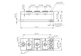
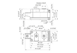
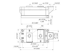
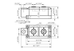
Abmessungen von Thyristor-Modulen MT3, MT4, MT5:
Anschlussplan für Thyristor-Module MT3, MT4, MT5:
Empfehlungen für die Montage von Leistungsmodulen
Kühlkörper- und Oberflächenspezifikationen, Vorbereitung
Um einen guten thermischen Kontakt zu gewährleisten und die in den Datenblättern angegebenen Werte für den thermischen Kontaktwiderstand zu erhalten, muss die Kontaktfläche des Kühlkörpers sauber und frei von Staubpartikeln sein. Es ist sinnvoll, die Montagefläche des Kühlkörpers unmittelbar vor der Montage mit Tüchern und einem Alkoholreiniger, z. B. Isopropanol, zu reinigen. Die folgenden mechanischen Spezifikationen müssen eingehalten werden:
– Unebenheiten im Montagebereich des Kühlkörpers müssen ≤ 50μm per 100 mm
– Rauhigkeit Rz: < 10 μm
– Keine Schritte > 10 μm

Spezifikation der Kühlkörperoberfläche |
Auftragen von Wärmeleitpaste
Es wird empfohlen, die Wärmeleitpaste im Schablonendruckverfahren aufzubringen. Es wird empfohlen, eine Wärmeleitpastendicke im Bereich von 50 μm bis 100 μm zu verwenden. Das Auftragen von Wärmeleitpaste mit einer Walze wird für die Massenproduktion nicht empfohlen, da die Reproduzierbarkeit einer optimierten Wärmeleitpastendicke nicht gewährleistet werden kann.
Anzugsmoment am Kühlkörper MS
Zur Befestigung der Leistungsmodule wird die Verwendung von Stahlschrauben in Kombination mit geeigneten Unterlegscheiben und Federringen oder Kombischrauben dringend empfohlen. Das im Datenblatt angegebene Drehmoment muss eingehalten werden.
Es wird ein Voranziehdrehmoment und ein Nachziehen auf den vorgegebenen Drehmomentwert empfohlen. Für den Schraubvorgang muss die Drehzahl begrenzt werden und eine weiche Drehmomentbegrenzung wird empfohlen, um Drehmomentspitzen zu vermeiden, die bei Druckluftschraubern auftreten können.

Beispiel für eine Montagereihenfolge |
Die Schrauben müssen in mehreren Schritten über Kreuz mit gleichem Drehmoment angezogen werden, bis der angegebene Drehmomentwert erreicht ist. MS erreicht worden ist.
 Warum Sie sich für AS ENERGITM
- Eigene Produktionsanlagen, einschließlich der Produktion von Halbleitersiliziumchips
- Europäische Marke - 100% Qualität, günstiger Preis, kurze Produktionsfristen
- Über 20 Jahre Erfahrung in der Halbleiterindustrie
- Kunden aus mehr als 50 Ländern vertrauen uns
- 20000 Artikel in der Produktlinie Ströme von 10A bis 15000A, Spannungen von 100V bis 9000V
- Wir produzieren Analogen von Produkten anderer Hersteller
- Garantierte zertifizierte Qualität, Garantiezeit des Betriebs - 2 Jahre
Qualitätsgarantie
Unsere Produkte sind zertifiziert und entsprechen internationalen Standards.
Unser Unternehmen gewährt eine Qualitätsgarantie für Produkte von 2 Jahren.
Auf Wunsch des Kunden stellen wir Konformitätsbescheinigungen, Zuverlässigkeits berichte, Datenblätter und technische Pässe zur Verfügung.
Jedes Produkt wird auf die Hauptparameter getestet und Testberichte der Parameter für jedes Produkt werden bereitgestellt.
Geografie der Partnerschaft
Das Unternehmen AS ENERGITM fertigt und liefert Leistungshalbleiter in mehr als 50 Länder auf der ganzen Welt.
Logistik und Lieferung
Wir liefern unsere Produkte in die ganze Welt mit den Diensten von Logistikunternehmen: DHL, TNT, UPS, EMS, Fedex, Aramex.
Die Lieferung der Produkte kann mit allen Transportmitteln erfolgen: Luft, See, Schiene und Straße.

AS ENERGITM Semiconductors Manufakturen
Unsere Produktpalette umfasst Gleichrichterdioden, Phasensteuerthyristoren in Scheiben- und Bolzen Bauweise, Avalanche-Dioden und Thyristoren, schnell schaltende, Hochfrequenz-Thyristoren, schnelle Erholungs-, Schweiß- und Rotordioden, Triacs, Brückengleichrichter, Leistungsmodule (Thyristor, Diode, Thyristordiode, IGBT) und Luft- und Wasserkühlkörper dazu.
Leistungsdioden und Thyristoren werden für Ströme von 10A bis 15000A, Spannungsbereich von 100V bis 9000V hergestellt.
Leistungsdioden- und Thyristormodule werden von 25A bis 1250A, Spannungsbereich 400V - 4400V produziert.
Das Angebot an Leistungshalbleitern umfasst auch gleichwertige, Ersatz-, analoge und alternative Halbleiterbauelemente globaler Hersteller.
Ausgewählte Produkte:
Keine Daten.

 IT
IT